
 日本語
 Русский
 España
 عرب .

Aluminum Foil Insulation Membrane: Reflective Performance and Material Selection
2026-11-02
Reflective performance in a building assembly is set by three numbers: surface emittance, the depth of the enclosed air space the foil faces, and the permeance class of the finished laminate. Only the first belongs to the aluminum. The other two belong to how the membrane is built and how it is installed, which is where most specification errors start.
Emittance Is the Number That Sets Reflective Performance
A clean aluminum surface with total normal emittance between 0.03 and 0.05 reflects about 95 percent of the long wave radiation arriving from a warmer surface, and that figure, not foil thickness or visible shine, determines the radiant share of heat flow.
Emittance and reflectance describe the same property from opposite sides: for an opaque surface at a given wavelength the two add to 1. The measurement is made in the thermal infrared, roughly 2.5 to 50 micron wavelength, using ASTM E408 or ASTM C1371. A membrane that looks bright under workshop lighting can still measure 0.15 after handling, because dust, release agents and finger oils raise emittance quickly.
A radiant barrier is a low emittance surface installed facing an enclosed air space. ASTM C1313 covers sheet radiant barriers for building construction and requires the emittance value and its test method to be reported. A datasheet that claims 95 percent reflection without stating a measured emittance and the method behind it cannot be compared with a competitor's product.
| Surface condition | Typical total normal emittance | Radiant share reflected |
| Bright foil, clean, facing a closed cavity | 0.03 - 0.05 | 95 - 97 percent |
| Foil with light site dust | 0.10 - 0.20 | 80 - 90 percent |
| Foil facing an open, dusty cavity | 0.25 - 0.40 | 60 - 75 percent |
| Metallized film on PET | 0.05 - 0.15 | 85 - 95 percent |
| Plain polyethylene film | 0.85 - 0.90 | 10 - 15 percent |
Field condition therefore matters more than factory condition. A foil facing a closed, clean cavity holds its emittance for the life of the building, while a foil facing an open cavity accumulates dust and loses reflective value before handover. Dust loading is the main mechanism that degrades emittance after installation, and it is a detailing problem rather than a product defect.
Air Space Depth Decides the Result, Not Foil Gauge
A reflective membrane reaches its declared thermal performance only when it faces an enclosed, still air space. EN 16012 requires a reflective insulation declaration to state the air space thickness and heat flow direction used, and a membrane clamped against sheathing or insulation loses most of the radiant benefit because the surface no longer radiates across a cavity.
Heat crosses a cavity by three paths: radiation between surfaces, convection in the air, and conduction through contact points and fasteners. The foil suppresses only the radiative path. ASHRAE Fundamentals tabulates air space thermal resistance by thickness, orientation and heat flow direction, and the curve flattens once the cavity passes roughly 25 mm, so battens deeper than that add little.
Cavity depth is also the variable most often missing from a datasheet. Two membranes built from identical 7 micron foil can carry declared thermal resistance values that differ by a factor of two, purely because one declaration used a shallow cavity with horizontal heat flow and the other used a deep cavity with downward heat flow.
Foil gauge governs durability, not reflectance. Once the aluminum layer is continuous, moving from 7 micron to 12 micron changes tensile strength, tear resistance and puncture behaviour, while emittance stays in the same band. Foils below about 6 micron are more exposed to pinholes during lamination, and pinholes affect vapor resistance and long term integrity rather than reflective performance.
The Carrier Fabric Sets Strength, Handling and Vapor Class
In a laminated reflective membrane the aluminum layer performs the optical function and the carrier performs the mechanical and vapor function, so substrate selection decides how the product survives site handling and which permeance class it lands in.
Jiangsu Aotelong New Materials Co., Ltd., based in Yangzhou in Jiangsu Province, builds its reflective vapour barrier range on four carriers: woven cloth, nonwoven fabric, kraft paper and multilayer film constructions. Each carrier appears in several composite builds under its own product code, which is the practical way a specifier matches a membrane to a steel frame wall, a timber roof or an interior lining.
| Carrier | Mechanical contribution | Typical use | Watch point |
| Woven cloth composite | High tensile and tear strength, resists wind load | Wall and roof underlay on steel and timber frames | Coarse surface holds dust if left exposed |
| Nonwoven composite | Even bonding, clean surface, light cushioning | Interior linings and panel facings | Lower tear strength than woven carriers |
| Kraft paper composite | Stiff, printable, treated grades resist ignition | Interior reflective linings | Loses strength when wetted, must stay dry |
| Multilayer film composite | Highest vapor resistance and puncture resistance | Roof and wall assemblies needing tight control | Heavier rolls, stricter taping discipline |
| Reinforced foil | Puncture and abrasion resistance | Industrial and steel frame cladding | Stiffness complicates tight radius detailing |
Product codes usually encode the build: a nonwoven composite such as AN100 pairs a nonwoven carrier with an aluminum film, a reinforced grade such as APR90 adds a scrim for puncture resistance, and a multilayer construction such as AWN140 stacks several functional layers behind the foil. The code is not decoration; it is the only reliable way to compare two offers that both arrive labelled aluminum foil insulation membrane.
 AN100 Aluminum Film, PE, and Nonwoven CompositeThe AN100 code identifies a lightweight three-layer aluminum-film, PE, and nonwoven build for comparing reflective, moisture-resistant composites used in insulation facing and protected envelopes.View Product →
 APR90 Heat-Resistant Reflective Vapour Barrier with PET MeshA reinforced 90 g/m² vapour barrier with PET mesh and over 90% solar reflectance for roof, wall, and floor insulation where tear strength matters.View Product →
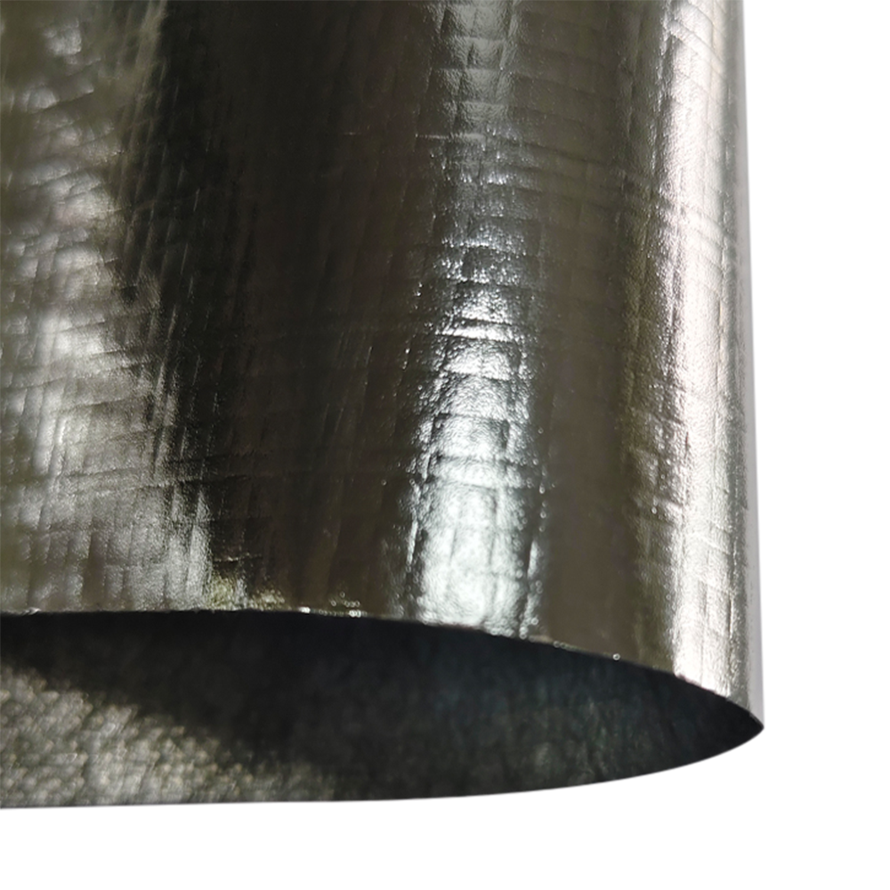 AWN140 Multilayer Reflective Film with Woven and Nonwoven LayersA 140 g/m² three-layer radiant barrier with high tensile and tear strength for roofs, walls, and envelopes; not classified as a vapor barrier.View Product →
Vapor Class Decides Placement, Not Product Selection
Aluminum foil laminated to a carrier is a Class I vapor retarder, with permeance at or below 0.1 perm when tested to ASTM E96, which makes membrane position in the assembly more consequential than the brand of foil used.
The classes are derived from ASTM E96 permeance and applied by the International Residential Code as Class I at 0.1 perm or less, Class II between 0.1 and 1.0 perm, and Class III between 1.0 and 10 perm. A foil membrane sits firmly in Class I. A micro-perforated foil-faced underlay can be pushed toward Class II, which is why perforation is a design decision rather than a manufacturing shortcut.
| Class | Permeance to ASTM E96 | Typical membranes |
| Class I | 0.1 perm or less | Foil faced membranes, foil faced sheathing, polyethylene sheet |
| Class II | 0.1 to 1.0 perm | Kraft facing and some coated membranes |
| Class III | 1.0 to 10 perm | Vapor retarder paints and some house wraps |
| Not classified | Above 10 perm | Water resistive barriers and most underlays |
Two Class I layers on both faces of a framed wall form a double vapor barrier. Moisture that enters the cavity during construction, or leaks in later, has no direction to dry, and the assembly then depends on how fast the cavity can equalize rather than on the reflective surface. Where foil-faced sheathing already exists, the interior membrane should be reclassified, perforated or removed.
A foil membrane is also not a waterproofing layer. It resists vapor diffusion and, depending on the carrier, liquid water, but the drainage plane and the vapor control layer remain separate functions. When a project tries to merge the two, a look at the different types of waterproofing used in construction is a quicker correction than a site inspection.
Six Checks Before Approving a Reflective Membrane Sample
Six documents decide whether a reflective membrane offer is genuinely comparable: foil gauge and continuity, an emittance test report, a permeance value with its ASTM E96 method, mechanical data, fire classification of the full composite, and third-party factory evidence.
- Foil gauge stated in micron, with a pinhole or light transmission check run on the finished laminate rather than on the raw foil.
- Total normal emittance measured to ASTM E408 or ASTM C1371 on the finished product and reported as a maximum value, not as a marketing percentage of reflection.
- Permeance to ASTM E96 with the method named, because wet cup and desiccant results are not interchangeable on a foil-faced composite.
- Tensile and tear data to ASTM D5034 or EN 12311-2, plus nail tear where the membrane is used as an underlay pulled over battens.
- Reaction to fire to EN 13501-1 or ASTM E84 quoted for the composite, since a foil facing can shift flame spread relative to the bare carrier.
- Third-party factory inspection and batch traceability, which matter most on export projects where CE marking and declaration of performance are contract conditions.
Installation Details That Keep or Erase the Reflective Gain
Reflective performance survives installation only when the cavity stays open, the foil faces that cavity, and the membrane stays continuous. Each of those three conditions fails at predictable points on site.
- Counter battens hold the cavity depth used in the thermal declaration.
- Foil faces the enclosed cavity, never the sheathing.
- Laps taped with a foil-compatible tape over a clean, dry surface.
- Services and penetrations sealed before the cavity closes.
- Roof underlay laid along the vent path the manufacturer specifies.
- Membrane pulled tight against insulation, closing the cavity to near zero.
- Untaped laps that turn vapor control into an air leakage path.
- Foil surface left dusty or oil-contaminated before closing.
- A second Class I layer added on the interior side.
- Staples and cable penetrations left unsealed.
Direct Answers to Common Specification Questions
Does a thicker aluminum foil reflect more heat?
No. Once the foil layer is continuous, total normal emittance stays in the 0.03 to 0.05 band, and a 7 micron foil measures the same as a 12 micron foil. Extra gauge improves tensile strength, tear resistance and puncture behaviour, which matters during handling but not to the radiant balance of the assembly.
What emittance value should a specification state?
State a maximum total normal emittance of 0.05 measured to ASTM E408 or ASTM C1371 on the finished composite, then pair it with the air space depth and heat flow direction used in the EN 16012 declaration. An emittance limit without those cavity conditions cannot be verified on site.
When is a foil membrane the wrong choice for a roof?
When the roof build-up has no direction to dry. A Class I foil underlay fixed directly over a cold deck traps moisture on the underside of the foil unless a ventilated cavity sits above the insulation, so the permeance of the underlay must be checked against the roof type rather than chosen for its reflective value alone.
How much thermal resistance can a reflective membrane add to a wall?
Its contribution is limited to the radiant fraction across the cavity it faces, which depends on cavity depth, heat flow direction and emittance. EN 16012 declarations express exactly that contribution for defined air spaces. Everything beyond it has to come from insulation thickness, so a foil membrane is not a substitute for insulation.


© 2024 Jiangsu Aotelong New Materials Co., Ltd.

-
+86-0514-87539226 (Tel)
+86-514-87539218 (Fax)
Tiancheng Road, Shatou Industrial Park, Guangling District, Yangzhou City, Jiangsu.